[01]
arXiv
• preprint Wi-Fi Sensing & Network Intelligence
DoDTrack: Indoor Mobile Devices Tracking via Difference-of-Doppler
arXiv Preprint , Aug, 2026.
Indoor tracking of active wireless devices is important for smart buildings, industrial automation, and location-based services. Existing Doppler-based tracking methods often require the transmitter's starting position or additional sensing information such as angle-of-arrival (AoA) or time-of-flight (ToF), increasing deployment complexity and hardware cost.
DoDTrack addresses this limitation by using Difference-of-Doppler (DoD) measurements as the only sensing observable. A single receiver with spatially distributed antennas observes the uplink signal of a moving device. Because all receive RF chains share the same oscillator, common carrier-frequency and sampling-frequency offsets can be suppressed across antenna pairs. The system then reconstructs both the unknown starting position and the complete trajectory through joint optimization.
The main objectives are:
DoDTrack is designed for indoor environments where GNSS is unavailable and conventional localization methods may require additional bandwidth, synchronization, or infrastructure. Typical deployments include smart spaces, industrial facilities, indoor robots, and other systems that need continuous tracking of active wireless devices.
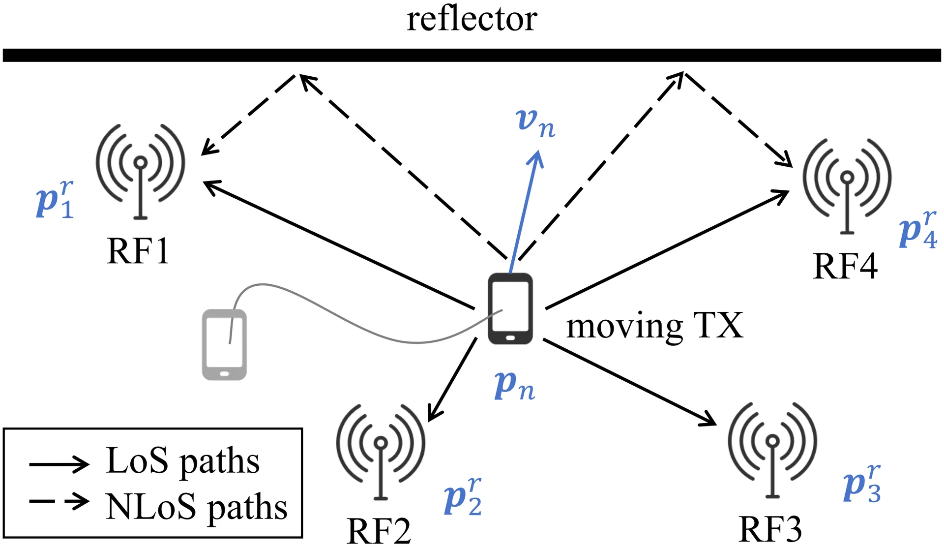 Figure 1: Representative indoor tracking scenario with a moving active transmitter and four distributed receive antennas deployed around the sensing area.
The receiver can be implemented as a dedicated sensing node or integrated into an access point or base station operating in uplink mode. The antenna positions are known in advance, while the transmitter starting position is not required. Since DoDTrack relies on Doppler differences rather than absolute propagation delay, only a narrowband portion of the communication signal is needed for sensing.
The system contains three main processing stages:
Difference-of-Doppler Extraction: Signals received by different antennas are conjugately multiplied. Since the receive RF chains share the same oscillator, this operation suppresses common carrier-frequency offset and sampling-frequency offset. Short-Time Fourier Transform (STFT) processing is then used to detect the dominant LoS Doppler-difference component from the time-frequency spectrum.
DoD-Based Trajectory Formulation: For receive antennas, each observation interval provides pairwise DoD measurements. The measured DoDs are compared with analytical values calculated from the candidate transmitter trajectory. The reconstruction is formulated as an MMSE problem:
where contains the measured DoDs and contains the DoDs predicted from trajectory .
Alternating Trajectory Reconstruction: Given a candidate starting position, an Extended Kalman Filter (EKF) estimates the trajectory shape and velocity sequence. The starting position is subsequently refined by gradient descent. Multiple initial grid points are evaluated to reduce sensitivity to local optima, and the solution with the minimum DoD reconstruction error is selected.
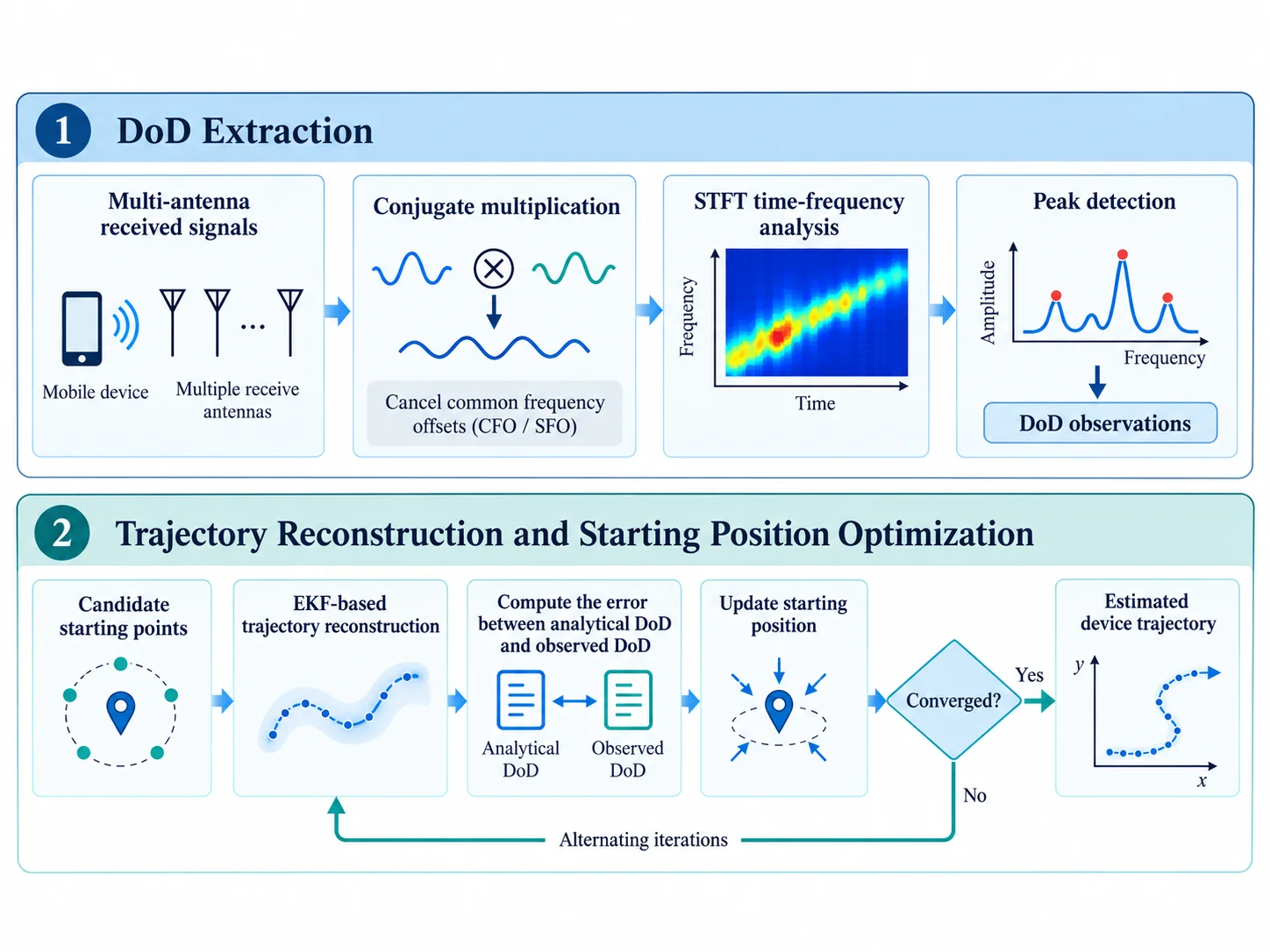 Figure 2: Processing pipeline of DoDTrack, including pairwise signal combination, STFT-based DoD detection, EKF-based trajectory estimation, and gradient-descent refinement of the unknown starting position.
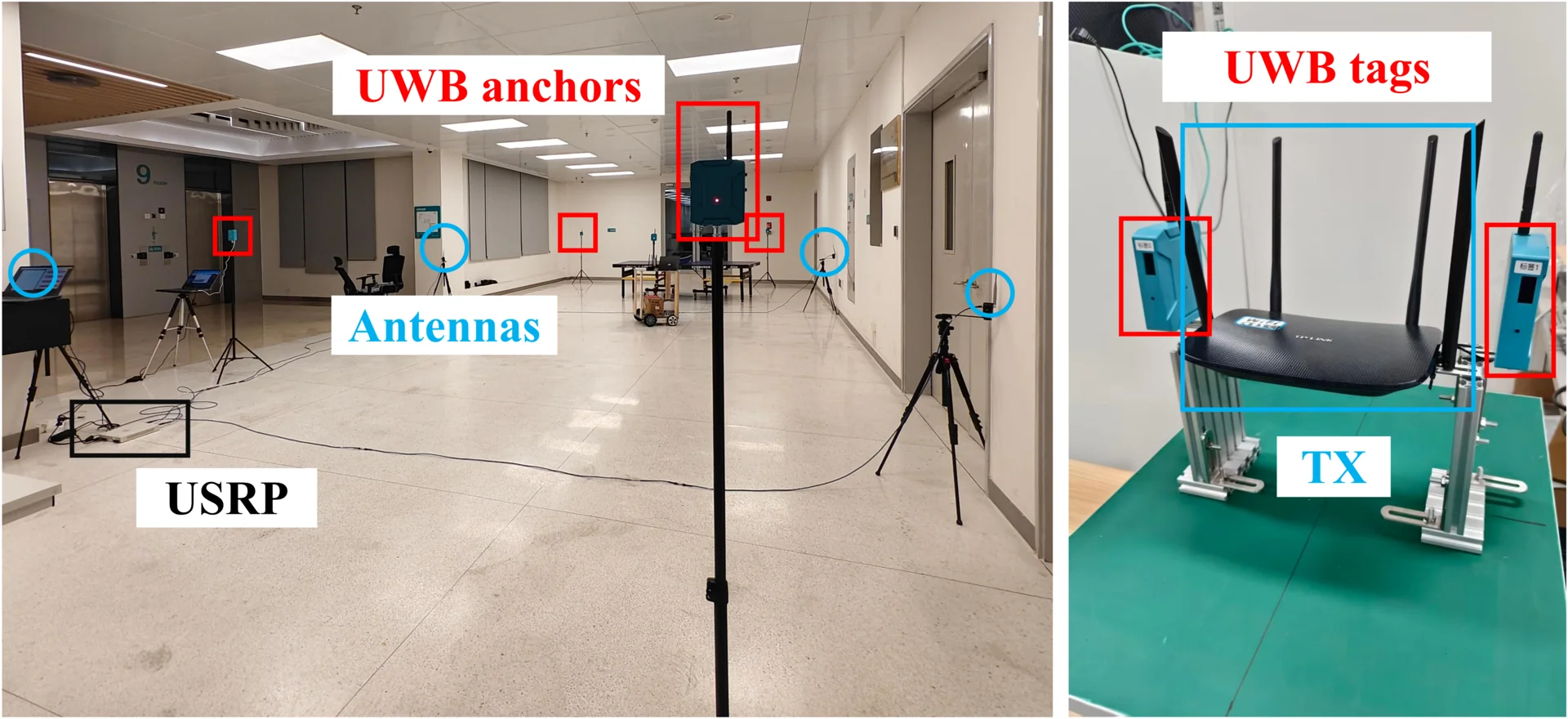
We implemented DoDTrack on a practical indoor testbed using a commercial Wi-Fi router and a four-channel USRP receiver.
| Parameter / Component | Specification |
|---|---|
| Transmitter | TP-LINK TL-XDR1520 Wi-Fi router |
| Receiver | Four-channel USRP-2953R |
| Receive Antennas | 4 distributed omnidirectional antennas |
| Carrier Frequency | 5.32 GHz |
| Signal Bandwidth | 20 MHz |
| Receiver Sampling Rate | 2 MHz |
| Sensing Area | Approximately |
| Ground Truth | UWB system with approximately 10 cm positioning accuracy |
The experiments contain 80 trajectories with circular, rectangular, and random shapes. A 0.5 s STFT window is used, providing 2 Hz frequency resolution for DoD extraction. The reconstructed trajectories closely follow the UWB ground truth even when the transmitter starting position is unknown.
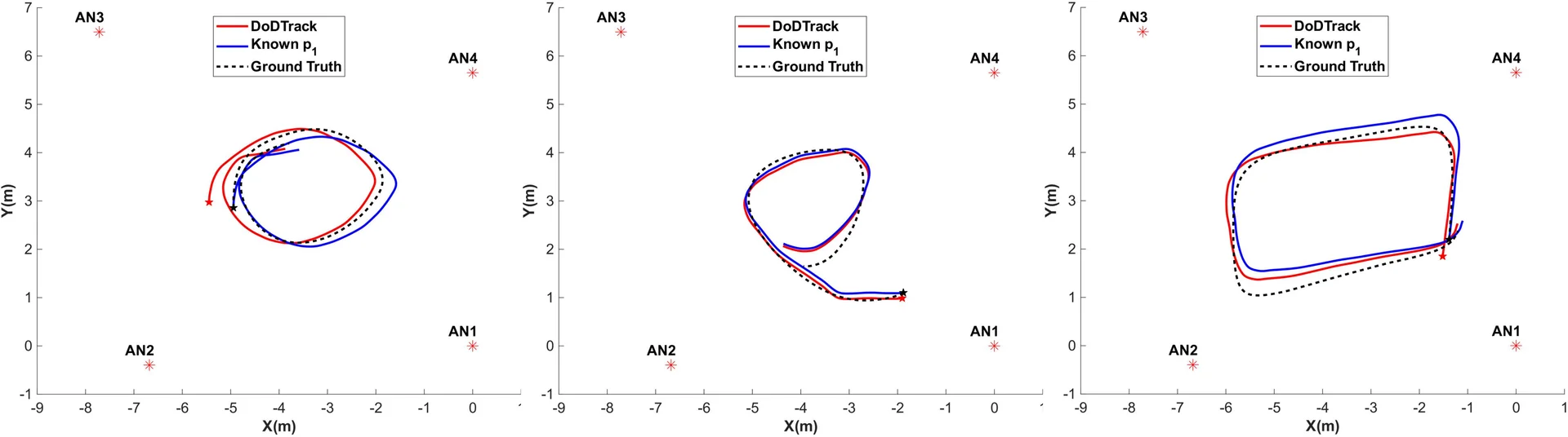 Figure 3: Representative reconstruction results for circular, rectangular, and random trajectories, comparing DoDTrack estimates with ground-truth paths.
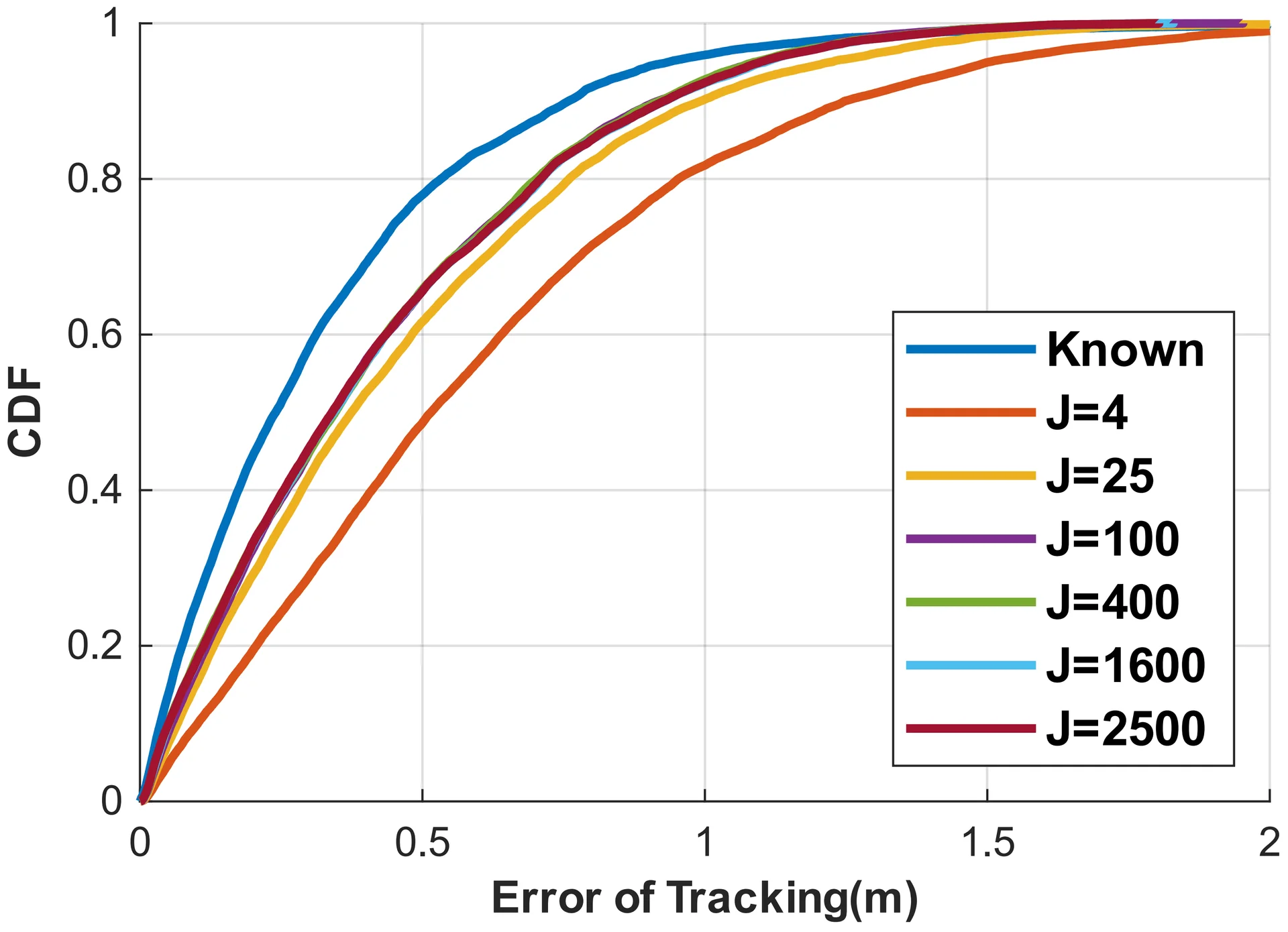 Figure 4: Cumulative distribution function of tracking error under different numbers of starting-position initialization grid points.
The evaluation further shows that increasing the number of initialization grid points improves accuracy only up to a saturation region. A grid size of provides a practical balance between tracking precision and computational cost.